Ideal Transformer

Although it is non-realistic let's assume an idealistic transformer with the following assumptions:
- The resistance of the coil is zero
- The core of the transformer is highly permeable (no MMF required to setup flux).
- No leakage flux (all the flux links the secondary coil)
- No eddy current or hystereris loss.
- Interwinding capacitance effects are neglected.
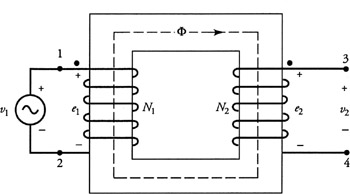
The induced voltage in coil#1 (primary winding) can be expressed as:
$$e_1 = N_1 \frac{d\Phi}{dt}$$ Similarly, the induced emf in Coil#2 (secondary winding)is:
$$e_2 = N_2 \frac{d\Phi}{dt}$$ As we assumed, there is no leakage flux, the flux linking both of the coils are equal, thus:
$$\frac{V_1}{V_2} = \frac{e_1}{e_2} = \frac{N_1}{N_2}$$ which implies; the higher the number of turns the higher the induced voltage.
The ratio of the currents are inversely proportional to turns ratio. There are two ways to verify this:
Firstly, we assumed there are no losses in the transformers, so the input power should be equal to the output power.
$$P{in} = P{out}$$$$V_1 I_1 = V_2 I_2$$$$\frac{V_1}{V_2} = \frac{I_2}{I_1}$$ From above, we already showed that the ratio of number of turns is equal to the ratio of the induced voltages. Thus;
$$\frac{N_1}{N_2} = \frac{I_2}{I_1}$$$$N_1 I_1 =N_2 I_2$$ The same relation can be obtained from the magnetic circuit. As the permeaability of the core is assumed to be infinite, the magnetic voltage drop is zero (H=0) in the core. Thus, the primary and secondary MMF should be equal:
$$\mathrm{F_1}=\mathrm{F_2}$$$$N_1 I_1 =N_2 I_2$$
Transformer ratio
The ratio of primary to secondary number of turns is called a-ratio or transformation ratio
$$a = \frac{N_1}{N_2}$$ Sometimes it is showed as a:1 (e.g. 15:1, 1:10 transformer). (a > 1) for step-down transformers, (a < 1 ) for step-up transformers.
Schematic
Ideal transformer are represented with the following symbol:
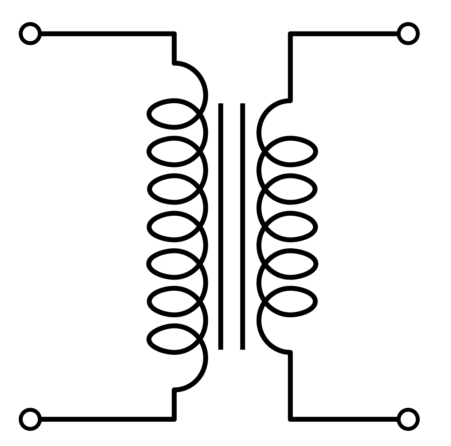
Dots are used to represent the polarity of the transformer:
![]()
Dots on the same side represent, the primary and secondary voltages are in-phase. Dots in the opposite side represent there is a 180 degree shift between primary and secondary.
Ideal Transformer with Load
Consider the previous figure. A load ((Z_L)) is connected to the transformers secondary winding. The power in the load can be expressed as:
$$P_L = V_S I_S$$ The impedance of the load can be expressed as:
$$Z_L = \frac{V_S}{I_S}$$ If we put the transformer and load in a black box, for the primary voltage source, the equivalent impedance of the circuit is the ratio of primary voltage to primary current.
$$Z_P = \frac{V_P}{I_P}$$ which can be expressed using secondary voltage and current as follows:
$$Z_P = \frac{\frac{N_P}{N_S}V_P}{I_S \frac{N_S}{N_P}}$$$$Z_P =\left( \frac{N_P}{N_S}\right)^2 Z_S$$ Or using "1" for primary substution and "2" for secondary:
$$Z_1 =\left( \frac{N_1}{N_2}\right)^2 Z_2$$
Transformations between primary and secondary:
Assume the transformer ratio is (a) (i.e. a:1):
From Secondary to Primary Winding
| Referred to Primary | Actual Value |
|---|---|
| (V_2' = a V_2) | (V_2) |
| (I_2' = I_2/a ) | (I_2) |
| (Z_2' = a^2 Z_2) | (Z_2) |
From Primary to Secondary Winding
| Actual Value | Referred to Secondary |
|---|---|
| (V_1) | (V_1' = V_1 / a) |
| (I_1) | (I_1' = a I_1 ) |
| (Z_1) | (Z_1' = Z_1 / a^2) |