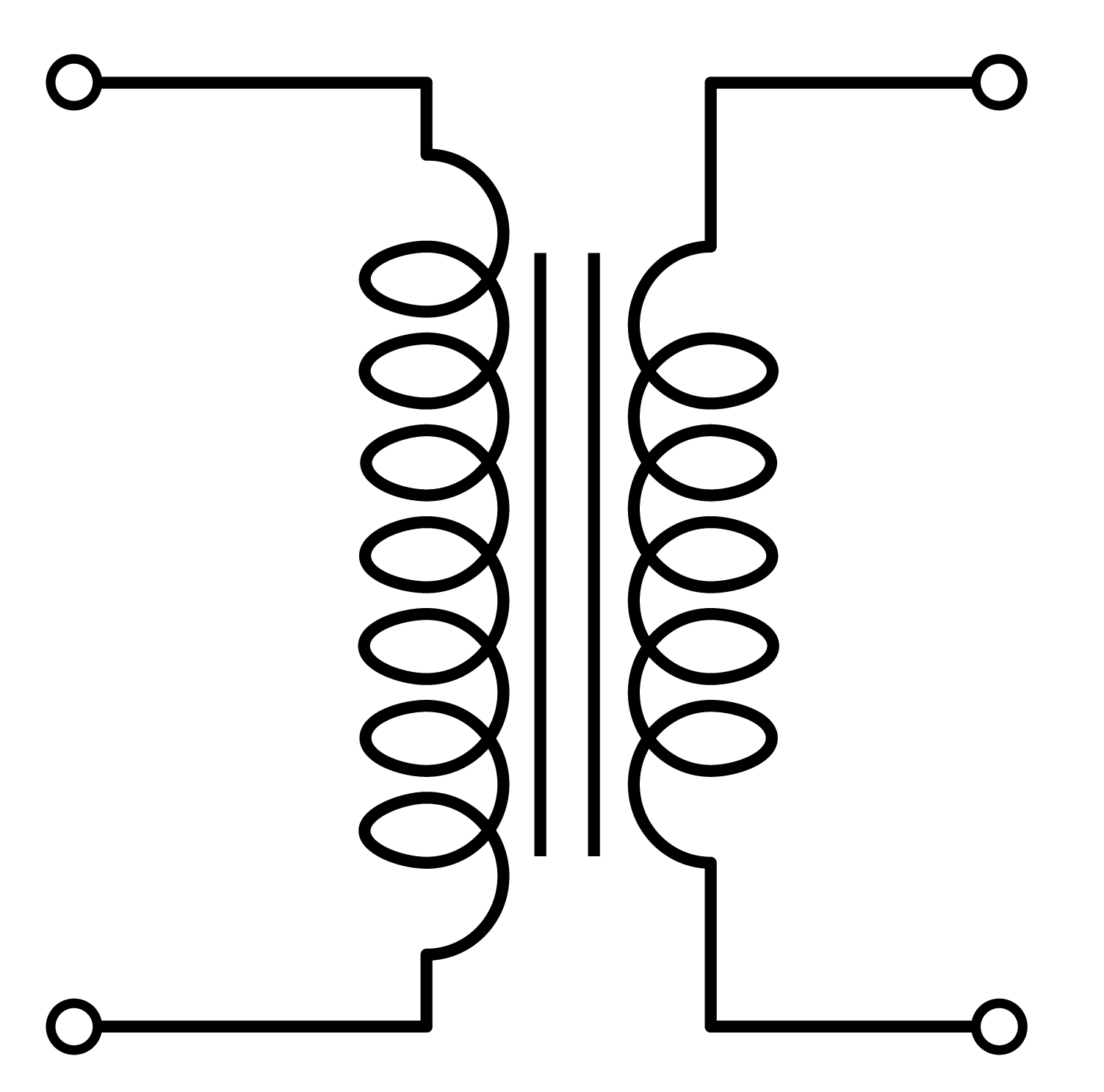
Practical Transformer
We covered the ideal transformer in the previous section. We made lots of assumptions to simplify the transformer to an ideal unit that steps-down or steps-up the applied AC voltage:
However, we need to consider other parameters to obtain a more realistic representation:
- Coil Resistance: The resistance of the copper used in the primary and secondary winding is non-zero. The resistance is proportional to the length of the wire, hence to the number of turns.
- Some of the flux in the primary winding does not link the magnetic core and the secondary winding. This component is called the leakage flux.
- The permeability of the core is not infinite, thus there is some current (MMF) required to magnetize the core, which is called the magnetization current.
- The transformer core has a hysterisis B-H curve, which results in hysteresis loss. On top of that, there are eddy-current losses in the core. These two terms are shown with a resistive element in the equivalent circuit.
Thus, the actual transformer can be represented using an ideal transformer plus external resistances and impedances.
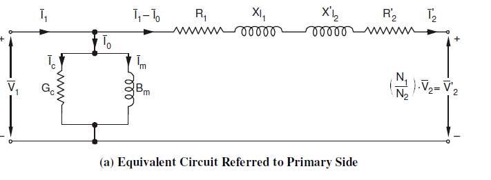
Equivalent circuit of an actual transformer:

Components:
- Winding Resistances ((R_1 ,\: R_2 )): This is the resistance of the copper used in the primary and secondary winding.
- Leakage Reactance ((X_{l})): This component represents the amount of flux that doesn't link the primary and secondary winding. In a good transformer design, this should be as small as possible.
- Magnetizing Reactance ((X_{m})): The current passes through this element represents the magnetizing current. (i.e. the H value in the operating B value).
- Core Loss Resistance ((Rcore)): This component represent the losses occur in the transformer core (i.e. hysteresis and eddy current losses).
Simplification of the Equivalent Circuit
1. Transfer secondary side parameters to the primary side

When referring the parameters they should be multiplied by the square of the turns ratio.
2. Move parallel branch to the source side
As the values of (R_1) and (X_l) is very small compared to (R_c) and (X_m). The voltage drop on the (R_1) and (X_l) can be neglected, and the parallel branch can be moved to the source side for simpler calculations.
3. Combine Primary and Secondary Series Components
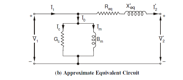
(R_{eq} = R_1 + R_2')
(X_{eq} = X_1 + X_2')
Solved Problems
Solved problems on transformers.